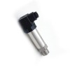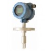
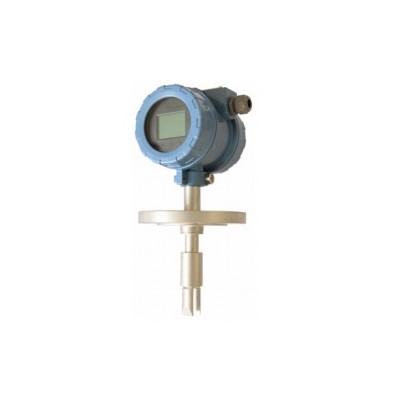
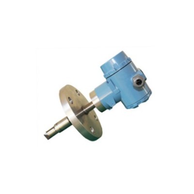
| : | Model: CJDMF-1-CR Description Insert Tuning Fork Density Meter is a new product which is based on the principle of vibration. Product design using plug-in installation, is widely used in the pipeline, the medium density detection, container open, closed container in the product in the mud slurry, evaporator, solvent separation, oil measurement and other fields. The density of the fluid directly dependents on vibration frequency which tuning fork receives when sensor inserts into media. Sensor’s built-in temperature sensor provides temperature compensation
Application CJDMF-1-CR insertion density meter could apply the on-line density testing. It could be applied in the product process controlling based on the basic parameters of density, or the mass controlling system as the solid percentage or the concentration for references.
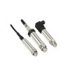
Feature Plug in design, plug and play, and continuous online measurement No moving parts, maintenance free, anti-corrosion design for specific conditions Temperature compensation Customize rod length The environment is not sensitive to vibration, and the short rod type is suitable for high pressure pipeline (maximum pressure 20Mpa)
Working Principle The sensor is based on the principle of component vibration, and the component part is a part of tuning fork immersed in measured liquid. The tuning fork induces vibration by a piezoelectric device fixed at one end of bottom of the fork. The vibration frequency is detected by two piezoelectric devices fixed at the other end of the fork, and then signal is amplified through the top of the circuit. The liquid density is closely related to the vibration frequency of measured liquid when measured liquid is streaming. When the measured liquid density changes, the vibration frequency of it also changes when the measured liquid is streaming.The density of the measured liquid can be calculated accurately by equation.
Technical Parameters
Calculation of Fluid Measurement V = Q / (1/4 *π*d2) Eg: flow rate20m3/h,pipe diameter 100mm V = 20 / 3600 / (1/4 * 3.14 * 0.1 * 0.1) = 0.7m/sec
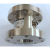
Installation 1. Demonstration of tubes installation To ensure the stabilities of measurement accuracy and the stable display, when the flow velocity of the liquid is higher than 0.5m/s: l If the size of the pipeline is higher than DN 100: It would be advisable to apply the necking installation on the vertical or horizontal pipeline. l If the size of the pipeline is smaller than DN 100: It would be advisable to enlarge of the pipeline and apply the necking Installation. In addition to this, it is necessary to have a certain distance of straight tube of both size to make sure the liquid flowing through the tubes are under the situation of laminar conditions, which is shown as the figure below.
Cautions
1. Do not cause any physical damage to the meter. 2. Do not measure incompatible fluid. 3. Do not operate the device if exceeding its rated pressure or maximum temperature. 4. Do not do any pressure test beyond the specified test pressure. 5. Do not expose the meter to excessive vibration (> 0.5 g continuous). 6. Do not modify this instrument in any way (mechanical or electrical), otherwise the factory warranty will be invalidated. This meter can be ordered with Zirconium wetted parts. In this case, mechanical modifications of any kind may produce a safety hazard and must not be performed. 7. Do not exceed the stated supply voltage range, otherwise the meter may be damaged and a hazard may exist. 8. Ensure all explosion-proof requirements have been applied. 9. Ensure the meter and associated pipe work are pressure tested to 1-1/2 times at the maximum operating pressure after installation. 10. Ensure the transmitter outer covers are tightened properly after wiring to maintain ingress protection. 11. Be aware of handling PFA-coated tines as the coating is not resistant to any impact. Always keep the protective cover on when the meter is not in use. 12. Maintain the meter in its original packaging. For the long-stem meters, ensure the transit cover secured by the grub screws.
Appendix I – Address Book of Modbus RTU
Demonstration 1. To prevent unnecessary issues which might occur, editing the address info is not recommended 2. Default setting for communication setting: Data bit: 8 Stop bit: 1 Check: None Baud rate: 9600 Station: 1 Protocol: Modbus RT
Model Selection
|
|||||||||||||||||||||||||||||||||||||||||||||||||||||||||||||||||||||||||||||||||||||||||||||||||||||||||||||||||||||||||||||||||||||||||||||||||||||||||||||||||||||||||||||||||||||||||||||||||||||||||||||||||||||||||||||||||||||||||||||||||||||||||||||||||||